Hydraulic Filtration Machine & Oil Filter | Hidroman
Hydraulic Filtration Machine and Hydraulic Oil Filtration Systems
Mobile Hydraulic Oil Filtration and Flushing Equipment – Hidroman
Clean hydraulic oil is essential for reliable hydraulic system performance, component protection and equipment service life. Solid particles, metal debris, dust and other contaminants can accelerate wear in hydraulic pumps, valves, motors, cylinders and precision control components. Uncontrolled contamination can lead to reduced performance, component damage and unplanned downtime.
Hidroman provides hydraulic filtration machines and engineering solutions for industrial plants, hydraulic service workshops, OEM machinery manufacturers and mobile maintenance teams. These solutions support hydraulic oil filtration, offline filtration and hydraulic system flushing applications.
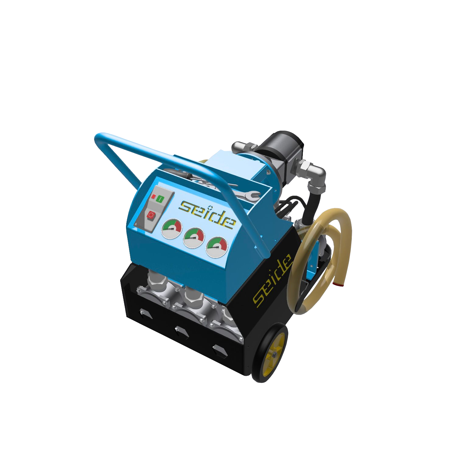
The Seide RK91 Mobile Filtration and Flushing Machine is designed for applications involving hydraulic oil cleaning, fluid transfer, particulate contamination control and suitable flushing procedures.
A properly selected filtration system helps maintain fluid cleanliness, protect hydraulic components and support preventive maintenance based on measurable oil-condition data.
Seide RK91 Mobile Hydraulic Filtration Machine
The Seide RK91 is a mobile filtration unit designed for hydraulic oil filtration, cleaning, transfer and suitable hydraulic flushing applications.
Its compact design allows it to be moved between machines and service locations. The unit can operate independently of the main hydraulic circuit as an offline filtration system or be connected to a hydraulic circuit for cleaning applications, provided that the circuit configuration and operating conditions are suitable.
Key Features
Mobile hydraulic oil filtration and flushing
Compact, portable design
Single-, two- or three-stage filtration configurations
Standard 60 µm, 25 µm and 10 µm filtration stages
Optional 5 µm final filtration
Optional electronic particle counter
Particle contamination monitoring according to ISO 4406 and NAS 1638 classifications
Minimes connections for direct measurement
Easy-to-replace filter elements
Integrated suction and return hoses
Suitable for hydraulic oil and lubrication systems
Designed for industrial maintenance and hydraulic service applications
Multi-Stage Hydraulic Oil Filtration
The appropriate filtration configuration depends on the required cleanliness level, fluid condition and hydraulic component requirements.
Three-Stage Filtration
60 µm → 25 µm → 10 µm
The three-stage configuration progressively removes particulate contamination. Larger particles are captured in the initial stage, while smaller particles are retained by the subsequent filter elements.
Two-Stage Filtration
25 µm → 10 µm
This configuration may be suitable for applications where coarse pre-filtration is not required.
Single-Stage Filtration
10 µm
A single-stage configuration for applications requiring one filtration stage.
Optional 5 µm Final Filtration
A 5 µm filter element can be selected as an optional final stage when finer filtration is required.
Filter selection should not be based on micron rating alone. System flow rate, oil viscosity, component manufacturer's recommendations and the required ISO 4406 cleanliness level must also be considered.
Why Is Hydraulic Oil Filtration Important?
Hydraulic oil does more than transmit power. It also lubricates moving components and contributes to the operating conditions of the hydraulic system.
Particulate contamination can cause abrasive wear, particularly in components manufactured with tight internal clearances. Pumps, proportional valves, servo valves, hydraulic motors and other precision components can be sensitive to fluid contamination.
A properly planned hydraulic oil filtration program can help:
Reduce particulate contamination
Protect pumps, valves and hydraulic motors
Maintain the required fluid cleanliness level
Reduce contamination-related wear
Support preventive maintenance programs
Support longer fluid service life when the oil remains chemically suitable
Avoid unnecessary oil replacement
Reduce the risk of contamination-related downtime
Hydraulic oil should not be considered clean simply because it looks clear. Fine particles may be invisible to the naked eye. Particle counting and, where necessary, laboratory oil analysis provide a more reliable assessment of fluid condition.
Hydraulic Oil Filtration vs. Oil Replacement
Replacing hydraulic oil is not always the only solution when the main problem is particulate contamination.
When the oil is chemically suitable and the primary issue is solid contamination, a hydraulic filtration machine can circulate the fluid through filter elements and return the filtered oil to the reservoir or system.
This approach may be useful for:
Preventive hydraulic maintenance
Hydraulic service workshops
Manufacturing plants
Mobile maintenance teams
Hydraulic power units
Industrial machinery
Construction and mining equipment
Injection molding machines
Hydraulic press systems
Wind turbine hydraulic systems
OEM hydraulic machinery
Filtration does not correct every type of fluid degradation. Oxidation, chemical deterioration, incorrect viscosity, severe water contamination and additive degradation may require additional treatment or oil replacement.
Oil analysis should be considered before deciding whether filtration, water removal or replacement is the appropriate solution.
Hydraulic Filtration vs. Hydraulic Flushing
Hydraulic filtration and hydraulic flushing are related but different processes.
Hydraulic filtration primarily removes particulate contamination from hydraulic oil by passing the fluid through filter elements.
Hydraulic flushing is a controlled cleaning process intended to remove manufacturing, installation and maintenance contaminants from pipes, hoses, manifolds, reservoirs and hydraulic circuits.
Flushing is particularly important during:
New hydraulic system commissioning
Hydraulic pipe installation
Hose replacement
Pump, valve or other component replacement
Major system repairs
Hydraulic cylinder or motor replacement
Hydraulic system modifications
Reservoir and piping cleaning
For newly installed or rebuilt hydraulic systems, a suitable flushing procedure followed by filtration and cleanliness verification helps prepare the system for commissioning.
Particle Counting and Hydraulic Oil Cleanliness Monitoring
Visual inspection cannot reliably determine the particulate contamination level of hydraulic oil. This is particularly important in systems containing sensitive components such as servo and proportional valves.
The RK91 can be equipped with an optional electronic particle counter. Depending on the selected configuration, particle monitoring can provide measurable information about contamination within defined particle-size ranges.
Measurement results can be evaluated in relation to:
ISO 4406
NAS 1638
Relevant SAE cleanliness classifications
ISO 4406 Hydraulic Oil Cleanliness Classification
ISO 4406 is widely used to classify solid particle contamination in hydraulic fluids.
A code such as ISO 4406: 18/16/13 represents particle-count ranges for three particle-size categories:
≥4 µm(c)
≥6 µm(c)
≥14 µm(c)
Lower code values indicate lower particle contamination within the corresponding size range.
The target cleanliness level should be determined according to the hydraulic components installed in the system and their manufacturers' recommendations. Servo and proportional hydraulic systems generally require cleaner fluid than conventional hydraulic circuits.
NAS 1638 Cleanliness Classification
NAS 1638 evaluates hydraulic fluid contamination across different particle-size ranges:
5–15 µm
15–25 µm
25–50 µm
50–100 µm
Above 100 µm
Particle counts are evaluated separately for each range to determine the corresponding contamination class.
Why Does Particle Counting Matter?
Particle counting provides measurable data that can be used to compare oil cleanliness before and after filtration.
For commissioning and critical maintenance applications, recording cleanliness measurements helps document the condition of the hydraulic fluid and monitor filtration results over time.
Mobile Hydraulic Filtration for Preventive Maintenance
A mobile filtration unit can be an important part of a preventive hydraulic maintenance program.
Instead of waiting for contamination-related failures, maintenance teams can monitor fluid cleanliness and perform filtration when required.
A typical maintenance procedure may include:
Inspecting the hydraulic oil and operating conditions.
Taking an oil sample when necessary.
Measuring particulate contamination.
Comparing the result with the required cleanliness class.
Selecting the appropriate filter configuration.
Circulating the oil through the filtration unit.
Measuring the fluid cleanliness again.
Recording the results for maintenance documentation.
There is no universal filter-element replacement interval. The service interval depends on oil contamination, viscosity, filtration frequency, element capacity and operating conditions.
Seide RK91 Mobile Filtration Machine – Technical Specifications
The following specifications refer to the 80 L/min filtration configuration documented for this equipment.
| Specification | Technical value |
|---|---|
| Application | Hydraulic oil filtration and flushing |
| Pump flow rate | 80 L/min |
| Motor power | 1.1 kW |
| Motor speed | 1450 rpm |
| Number of filters | 3 |
| Filter capacity | 900 L/min × 3 (as stated in the technical document) |
| Dirt-holding capacity | 180 g × 3 (as stated in the technical document) |
| Machine weight | 65 kg |
| Electrical supply | 380–400 V |
Technical note: Filter capacity and dirt-holding capacity are reproduced as stated in the available technical documentation. They should be checked against the filter manufacturer's datasheet before being used as guaranteed performance values.
Filter Housing and Replacement Element Codes
| Filter housing code | Filter element code | Filtration rating |
|---|---|---|
| HDM112-05 | SDM5060-05 | 5 µm |
| HDM112-10 | SDM5060-10 | 10 µm |
| HDM112-25 | SDM5060-25 | 25 µm |
| HDM112-60 | SDM5060-60 | 60 µm |
Optional water-separating filter elements:
SDM5060-05S – 5 µm, water-separating version
SDM5060-10S – 10 µm, water-separating version
SDM5060-25S – 25 µm, water-separating version
SDM5060-60S – 60 µm, water-separating version
Additional Filter Element References
The available technical documentation also lists the following replacement filter elements:
| Filter element code | Filtration rating |
|---|---|
| S5.1280.115-05 | 5 µm |
| S5.1280.110-10 | 10 µm |
| S5.1280.125-25 | 25 µm |
| S5.1280.160-60 | 60 µm |
Before selecting a replacement element, check housing compatibility, flow rate, oil viscosity, pressure drop and the required cleanliness level.
Hydraulic Pipe Pickling and Flushing
Hydraulic pipes should be cleaned before a new system is commissioned. Manufacturing and installation processes may leave burrs, welding residues, rust and other contaminants on internal pipe surfaces.
Pickling is a chemical cleaning process used to remove manufacturing and installation residues and prepare the pipe surface for subsequent treatment.
Flushing involves circulating oil through the piping system under controlled flow conditions to remove remaining particulate contamination.
A properly designed cleaning process helps prepare hydraulic piping before sensitive components are placed into operation.
Hydraulic Pipe Pickling Stages
The pickling process described for this application consists of three main stages:
Acid cleaning: Performed using Picklane T60.
Neutralization: Performed using Passive T70.
Oil film formation: Hydraulic oil is circulated through the pipes to form a protective oil film on internal surfaces.
After acid cleaning and neutralization, hydraulic oil is circulated through the piping system. The system can then proceed to the flushing stage.
Equipment Used for Pickling
Three PVC tanks for acid, water and neutralization fluids
Acid pump
Heating unit
pH indicator
Tank dimensions and equipment capacity should be selected according to the size, length and process requirements of the hydraulic piping system.
How Is Hydraulic Flushing Performed?
Hydraulic flushing is performed after pipe manufacturing and installation to remove particulate contamination from internal pipe surfaces.
The objective is to establish suitable oil flow and turbulence so that particles can be dislodged and captured by the filtration system.
Required flow rate and pressure depend on pipe diameter, pipe length, oil viscosity and circuit configuration. Flushing loops may be required to achieve the necessary flow while controlling pressure loss.
Online Particle Measurement
Online particle measurements can be taken through Minimes test points installed in the hydraulic line.
Oil cleanliness is monitored during the flushing process. Once the required cleanliness level is reached, the flushing process can be completed, temporary connections removed and the system prepared for commissioning.
This measurement-based approach allows flushing results to be evaluated against recognized cleanliness classifications rather than visual inspection alone.
Hydraulic Flushing Equipment
Hydraulic flushing unit
3, 6, 10 and 20 µm filter elements
Hydraulic manifolds
Hydraulic hoses for flushing loops
Online particle counter
The total flushing time depends on pipe length, pipe diameter, oil viscosity, flow conditions and the amount of contamination in the system.
How to Calculate Hydraulic Flushing Flow Rate
Achieving suitable flow conditions inside the pipe is one of the key factors in hydraulic flushing.
The Reynolds number is used to evaluate whether flow is laminar, transitional or turbulent. A value around 2,320 may be used as a reference for the transition region. Flushing calculations may use higher target values, such as 4,000–5,000, depending on the application and available equipment capacity.
These values are not universal requirements for every hydraulic system. The actual target should be selected according to pipe geometry, fluid properties, flushing equipment and process requirements.
Hydraulic Flushing Flow Rate Formula
Q = Re × ν × d × 0.0000471
Where:
Q = Flow rate (L/min)
Re = Reynolds number
ν = Kinematic viscosity of the oil (mm²/s or cSt)
d = Internal pipe diameter (mm)
The required flushing flow rate should be evaluated using the largest internal pipe diameter in the circuit that must be cleaned.
Example Calculation – 2-Inch Pipe
Assume the following conditions:
Pipe size: 2 in (60.3 × 2.77 mm)
Internal diameter: 54.76 mm
Target Reynolds number: 4,000
Oil temperature: 60°C
Oil viscosity: 22 mm²/s
Using the formula:
Q = 4,000 × 22 × 54.76 × 0.0000471
Q ≈ 227 L/min
For this example, the calculated reference flushing flow rate is approximately 227 L/min.
Actual equipment sizing should also account for pipe length, connection losses, circuit configuration, pump capacity and changes in oil temperature.
Example – Pressure and Return Lines
Another example uses the following conditions:
Pressure line: 2 in (48.3 × 5 mm), internal diameter 38.3 mm
Return line: 2 in (60.3 × 2.77 mm), internal diameter 54.76 mm
Oil temperature: 60°C
Oil viscosity: 22 mm²/s
Reynolds number: 5,000
For the pressure line:
Q = 5,000 × 22 × 38.3 × 0.0000471
Q ≈ 198 L/min
For the return line:
Q = 5,000 × 22 × 54.76 × 0.0000471
Q ≈ 283 L/min
In this example, the return line requires the higher calculated flow rate. The actual flushing equipment capacity must be determined according to the circuit arrangement and which lines are cleaned simultaneously.
Flushing Flow Rates According to Pipe Diameter and Oil Viscosity
Flushing flow rate depends on both pipe internal diameter and oil viscosity. At the same pipe diameter, a change in oil viscosity changes the flow rate required to achieve a given Reynolds number.
The existing technical reference tables provide calculated flow rates for:
68 cSt oil at 55°C
46 cSt oil at 55°C
32 cSt oil at 55°C
The tables cover pipe sizes from DN6 to DN900 and include reference flow rates for Re 2300 and Re 4000.
Retain the original three technical tables in this section when publishing the updated page. The stated pipe dimensions are based on SCH 40 / STD wall thickness. Calculations should use the actual internal diameter, not the nominal DN size or outside diameter.
Second-Stage Hydraulic System Flushing
After the initial flushing process, the main hydraulic reservoir is filled with hydraulic oil.
During the second stage:
Hydraulic pumps are started and oil is circulated from the main reservoir.
Hydraulic blocks and piping are connected to the circuit.
Hydraulic cylinders and motors are kept disconnected where required by the flushing procedure.
Valves are operated to clean the relevant flow paths.
The return line is connected to the main return filters and then to the reservoir.
Once the required cleanliness level is achieved, temporary flushing connections are removed.
The hydraulic system is restored to its normal operating configuration.
Care must be taken during disassembly and reassembly to prevent new contamination from entering the system.
Reynolds Number and Hydraulic Flushing Flow Rate
The Reynolds number can also be calculated using:
Re = (21,220 × Q) / (ν × d)
Where:
Q = Flow rate (L/min)
Re = Reynolds number
ν = Kinematic viscosity of the oil (mm²/s)
d = Internal pipe diameter (mm)
This is the rearranged form of the flushing flow-rate formula above.
Example Calculation – 2-Inch Pipe
Assume:
Pipe size: 2 in (60.3 × 2.77 mm)
Internal diameter: 54.76 mm
Reynolds number: 4,000
Oil temperature: 60°C
Oil viscosity: 22 mm²/s
Re = (21,220 × Q) / (22 × 54.76)
Therefore:
Q ≈ 227 L/min
This gives the same result as the previous flow-rate calculation.
Applications of Hydraulic Filtration Machines
Hidroman hydraulic filtration and flushing solutions can be used in a wide range of industrial and mobile applications.
Industrial Hydraulic Systems
Suitable for hydraulic power units, presses, manufacturing machinery and industrial hydraulic circuits.
Hydraulic Service Workshops
The mobile design makes the filtration unit practical for hydraulic repair and maintenance workshops.
Mobile Hydraulic Maintenance
The equipment can be transported between machines and service locations for field maintenance applications.
OEM Machinery Manufacturers
OEM manufacturers can use filtration and flushing equipment during hydraulic system assembly and commissioning.
Construction and Mining Equipment
Suitable for hydraulic oil cleaning and preventive maintenance applications on heavy-duty mobile equipment.
Wind Power Applications
Hydraulic systems used in wind turbines and related equipment can benefit from controlled filtration and contamination monitoring.
Hydraulic Filtration Machine Manufacturer and Engineering Solutions – Hidroman
Hidroman provides hydraulic engineering solutions for industrial and mobile applications, including hydraulic filtration machines, mobile oil filtration units, hydraulic flushing equipment, hydraulic power units, hydraulic cylinders, hose equipment and test systems.
Selecting the correct filtration system requires more than choosing a filter micron rating. Flow rate, oil volume, viscosity, contaminant type, target cleanliness level and operating conditions must all be considered.
From standard mobile filtration units to application-specific filtration and flushing solutions, Hidroman evaluates equipment requirements according to the technical needs of each hydraulic system.
Prevent failures before they happen.
For a hydraulic filtration machine, mobile oil filtration unit or hydraulic flushing solution, contact Hidroman with your system flow rate, oil type, oil volume and target cleanliness level. Our team can help evaluate a suitable filtration configuration for your application.
Hidroman – Hydraulic Engineering and Filtration Solutions
Frequently Asked Questions
What is a hydraulic filtration machine?
A hydraulic filtration machine is a mobile or stationary unit designed to remove solid particulate contamination from hydraulic oil using filter elements. Oil is drawn from a reservoir or circuit, passed through the filters and returned to the system.
What is the difference between hydraulic filtration and flushing?
Filtration focuses on removing particles from hydraulic oil. Flushing is a controlled cleaning process intended to remove manufacturing and installation contaminants from pipes, hoses, manifolds and hydraulic circuits.
Can the RK91 filter hydraulic oil to 5 microns?
Yes. A 5 µm filter element can be selected as an optional final filtration stage, subject to the selected configuration and application requirements.
Can hydraulic oil cleanliness be checked visually?
No. Visual inspection cannot reliably determine particulate contamination. Particle counting and, where necessary, laboratory oil analysis should be used when a defined cleanliness class is required.
Which hydraulic oil cleanliness standard should be used?
ISO 4406 is widely used to classify particulate contamination in hydraulic fluids. NAS 1638 may also be used in relevant applications. The target cleanliness class should follow the hydraulic component manufacturer's recommendations.
How often should hydraulic oil be filtered?
There is no universal filtration interval. The frequency should be based on oil analysis, particle-count measurements, operating conditions and the equipment manufacturer's maintenance recommendations.
Does a hydraulic filtration machine remove water from oil?
Standard particulate filters are primarily designed to remove solid contamination. Water removal requires a suitable separation or dehydration solution based on whether the water is free, emulsified or dissolved. Water-separating filter elements should only be used within the manufacturer's specified operating conditions.
Can the RK91 be used for hydraulic system flushing?
Yes. The RK91 can be used for hydraulic oil filtration and suitable flushing applications. The required flow rate and cleanliness target must be determined according to pipe diameter, oil viscosity, circuit configuration and component requirements.
Request a Hydraulic Filtration Solution from Hidroman
Are you looking for a hydraulic oil filtration machine, mobile filtration unit or hydraulic flushing machine for your industrial equipment?
Share your application requirements with Hidroman. Our team can help evaluate a suitable filtration configuration based on oil volume, flow rate, viscosity, pipe diameter and target cleanliness level.
Hidroman – Hydraulic Filtration and Hydraulic Engineering Solutions
You May Also Be Interested In