


How to Use a Hydraulic Hose Press?
How to Use a Hydraulic Hose Press?
What you need is a hydraulic hose press for hydraulic hose manufacturing. The use of hydraulic hose press may differ according to its structure, but basically the hydraulic hose pressing diameter is the most important part for hydraulic hose manufacturing. The following information will be useful for you to calculate the hydraulic hose pressing diameter.
HOSE COUPLING PRESSING SIZE CALCULATION INSTRUCTIONS
AIM:
To ensure that the calculation is done correctly when calculating the hose coupling pressing size.
RESPONSIBLE:
Coupling Hydraulic Hose Team Leader
Hydraulic Hose with Union Crew Personnel
SCOPE:
It covers the pressing process of all hose unions to be pressed to the hose ends.
APPLICATION:
When pressing the hoses with unpeeled sockets conforming to the hose diameter standards EN 853 1SN and/or EN 853 2SN standard, check the fitting pressing table. Hose fitting is pressed to the extent in the box where the hose type and the hose diameter coincide.
When pressing peel-off sockets in accordance with hose diameter standards and hoses in EN 856 4SP and/or EN 856 4SH standards, check the fitting pressing table. Hose fitting is pressed to the extent in the box where the hose type and the hose diameter coincide.
If pressing will be done with sockets that are not included in the hose coupling pressing table, the following calculation is used.
DEFINITIONS:
D = Socket Outer Diameter
S = Difference Between Socket Inner Diameter and Hose Top Diameter (For No Peel Type Socket)
S1 = Difference Between Socket Inner Diameter and Hose Wire Top Diameter (For Peeled Type Socket)
d = Socket Inner Diameter
DP = Pressing Size
k = Embedding Size (Amount of Strain After Space Between Hose OD and Socket Inner Diameter)
t = Top Diameter Of Hose (For Non Peel Type Socket)
t1 = Diameter of Hose Wire Top (For Peeling Type Socket)
CALCULATING PRESSING DIMENSIONS FOR NON-PEEL TYPE SOCKETS
S = d-t
DP = D-S-k
Important Note: For the “k” dimension, refer to the Table of Deformation Amount after the Space Between Hose Outer Diameter and Socket Inner Diameter.
CALCULATING PRESSING SIZE FOR PEEL TYPE SOCKETS
S1 = d-t1
DP = D-S1-k
Important Note: For the “k” dimension, refer to the Table of Deformation Amount after the Space Between Hose Outer Diameter and Socket Inner Diameter.
AMOUNT OF DEFORMATION AFTER THE GAP BETWEEN HOSE OUTER DIAMETER AND SOCKET INNER DIAMETER (k)
|
HORTUM CİNSİ
HORTUM ÇAPI
|
R1T |
R2T |
4SP |
4SH |
OL7 OL8 |
MT1 MTH1 MTK |
MT2 MTH2 |
R6 |
R13 |
TEFLON |
|
3/16”
|
1,6 |
|
|
|
1,2 |
|
|
1 |
|
1 |
|
1/4 “
|
1,7 |
2 |
2 |
|
1,3 |
1,5 |
1,6 |
1,2 |
|
1,2 |
|
5/16”
|
1,8 |
2 |
|
|
1,5 |
1,5 |
1,7 |
1,5 |
|
1,3 |
|
3/8”
|
2,2 |
2 |
2 |
|
1,7 |
1,7 |
1,8 |
1,6 |
|
1,5 |
|
1/2"
|
2,5 |
2 |
2,5 |
|
1,8 |
1,8 |
2 |
1,7 |
|
1,5 |
|
5/8”
|
2,7 |
2,5 |
2,5 |
2,5 |
2 |
2 |
2,2 |
1,8 |
|
1,6 |
|
3/4"
|
3 |
2,5 |
2,5 |
2,7 |
2 |
2 |
2,5 |
1,8 |
|
1,7 |
|
1”
|
3 |
3 |
2,7 |
3 |
2,5 |
2,5 |
2,5 |
|
3 |
2 |
|
1 ¼”
|
3,5 |
3 |
3 |
3,5 |
|
|
|
|
3,5 |
|
|
1 ½”
|
3,5 |
3 |
3 |
3,5 |
|
|
|
|
3,5 |
|
|
2”
|
4 |
3,5 |
3,5 |
4 |
|
|
|
|
4,5 |
|
|
2 ½”
|
4,5 |
4 |
|
|
|
|
|
|
|
|
SEIDE S51 HYDRAULIC HOSE TIGHTENING MACHINE USER INSTRUCTIONS
AIM:
Working safely and error-free on the hose fitting pressing bench.
RESPONSIBLE:
Production Staff.
SCOPE:
Pressing the fitting on hydraulic hoses.
APPLICATION:
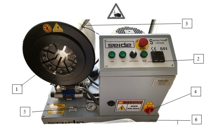
PARTS OF THE MACHINE
The main body on which the molds are attached
Control Board
Pressing Diameter Adjustment Micrometer
Electrical Connection Switch (it is used to cut and open the electrical current coming to the machine)
Pressure indicator
Hydraulic Oil Tank
CONTROL BOARD
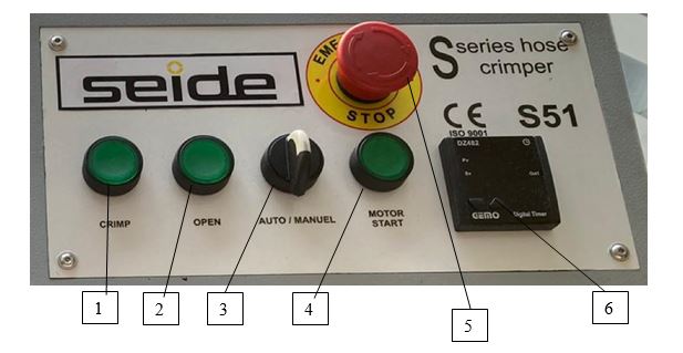
-
CRİMP : Hose Pressing Button
OPEN: Mold Open Button
AUTO/MANUEL: Manual Control- Automatic Control Button
ENGINE START: Machine Start Button
STOP: Emergency Stop
Machine Opening Distance Setting
MOLD SELECTIONOnly use original molds on the machine
Choose the die as close as possible to the clamping size.
The clamping range of the dies is as follows.
Take these dimensions into account when choosing patterns.D
TIGHTENING RANGE
15
15……18mm
18
18……21mm
21
21……24mm
24
24……27mm
27
27……33mm
33
33……39mm
39
39……45mm
45
45……51mm
51
51……57mm
57
57……66mm
66
66……75mm
MOLD REPLACEMENT
After the mold to be used is selected, the spring pins are pulled with the mold changing apparatus and the molds are set in place one by one. The molds are removed by pulling the spring pins with the help of the apparatus in the same way as the disassembly process.
MICROMETER SETTING
According to the diameter size to be pressed, micrometer adjustment is made with the help of the table below. Micrometer 0 Setting: 10.7mm.
Important Note: The hose pressing dimensions given are valid for the hose+coupling+sockets purchased from Hidroman. If a different material is used, the pressing dimensions will change.