

Hydraulic Hose Repair
The following instructions should be followed for hydraulic hose repair or new manufacturing.
HOSE LENGTH DETECTION
GOAL:
To make correct and safe determination of hose lengths.
RESPONSIBLE:
Workshop Staff
SCOPE:
Fitted Hoses
APPLICATION:
The sizes of selected fittings are calculated according to the chart below.
Since the hose will stretch a little during the pressing phase, the elongation length is added to the sum of the fittings, referring to the table below.
The hose length is calculated using the formula below.
LH = Hose Length LH = LT- (L1 + L2 + S)
S = Length of Extension
L1 = 1. Union Length
L2 = 2. Union Length
LT = Total Length
HOSE FITTING INSTALLATION INSTRUCTIONS
GOAL:
Making the installation of hose fittings correct and safe
RESPONSIBLE:
Workshop Staff
SCOPE:
Fitted hoses
APPLICATION:
The burrs on the ends of the cut hose are cleaned before mounting the unions.
After the cleaning process, a suitable socket is attached to the hose.
After inserting the socket, a distance is left between the support of the socket and the hose as much as the distance that the fitting will enter the locking projection.
Before mounting the fittings to the hose, the nozzle part of the fitting that passes into the hose is immersed in hydraulic oil and the fitting is inserted into the hose.
If both of the nozzles to be used in the hose are angled, the angle of the fittings is adjusted according to each other.
Hose fittings can also be assembled in UN10 Hose Fitting Machine. While assembling this machine, the cover of the machine is opened and the hose coupling attached to the hose is placed on the machine and the machine cover is closed. The hose fitting is mounted with the help of the arm on the cover.
HOSE FITTING PRESSING SIZE CALCULATION INSTRUCTIONS
GOAL:
Ensure that the calculation is done correctly when calculating the hose fitting pressing size.
RESPONSIBLE:
Fitted Hydraulic Hose Team Leader
Fitted Hydraulic Hose Team Staff
SCOPE:
It covers the pressing process of all hose fittings to be pressed onto the hose ends.
APPLICATION:
Fitting compression table should be checked when pressing hoses in accordance with the hose diameter standards without stripping EN 853 1SN and / or EN 853 2SN standard. Hose fitting pressing is performed to the extent that the hose type and hose diameter coincide.
Fitting press table should be checked for pressing of sockets with peeled sockets in accordance with hose diameter standards and hoses in EN 856 4SP and / or EN 856 4SH standards. Hose fitting pressing is performed to the extent that the hose type and hose diameter coincide.
If the hose fitting will be pressed with the sockets not included in the pressing table, the following calculation is used.

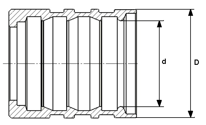
SYMBOL DEFINITIONS:
D = Socket Outer Diameter
S = Difference Between Socket Inner Diameter and Hose Upper Diameter (For Non-Stripping Type Socket)
S1 = Difference Between Socket Inner Diameter and Hose Wire Top Diameter (For Peeled Type Socket)
d = Socket Inner Diameter
DP = Pressing Size
k = Embedment Size (Amount of Strain After Gap Between Hose Outer Diameter and Socket Inner Diameter)
t = Hose Top Diameter (For Non-Stripping Type Socket)
t1 = Diameter of Hose Wire Top (For Peeled Type Socket)
CALCULATION OF PRESSING SIZE FOR NON-PEELING TYPE SOCKETS
S = d-t
DP = D-S-k
Important Note: For the "k" dimension, the Amount of Deformation After Gap Between Hose Outer Diameter and Socket Inner Diameter table should be used.
CALCULATION OF PRESSING DIMENSION FOR PEELING TYPE SOCKETS
S1 = d-t1
DP = D-S1-k
Important Note: For the "k" dimension, the Amount of Deformation After Gap Between Hose Outer Diameter and Socket Inner Diameter table should be used.
AMOUNT OF SHAPING AFTER THE GAP BETWEEN THE HOSE OUTER DIAMETER AND THE INNER DIAMETER OF THE SOCKET (k)
|
HORTUM CİNSİ
HORTUM ÇAPI
|
R1T |
R2T |
4SP |
4SH |
OL7 OL8 |
MT1 MTH1 MTK |
MT2 MTH2 |
R6 |
R13 |
TEFLON |
|
3/16”
|
1,6 |
|
|
|
1,2 |
|
|
1 |
|
1 |
|
1/4 “
|
1,7 |
2 |
2 |
|
1,3 |
1,5 |
1,6 |
1,2 |
|
1,2 |
|
5/16”
|
1,8 |
2 |
|
|
1,5 |
1,5 |
1,7 |
1,5 |
|
1,3 |
|
3/8”
|
2,2 |
2 |
2 |
|
1,7 |
1,7 |
1,8 |
1,6 |
|
1,5 |
|
1/2"
|
2,5 |
2 |
2,5 |
|
1,8 |
1,8 |
2 |
1,7 |
|
1,5 |
|
5/8”
|
2,7 |
2,5 |
2,5 |
2,5 |
2 |
2 |
2,2 |
1,8 |
|
1,6 |
|
3/4"
|
3 |
2,5 |
2,5 |
2,7 |
2 |
2 |
2,5 |
1,8 |
|
1,7 |
|
1”
|
3 |
3 |
2,7 |
3 |
2,5 |
2,5 |
2,5 |
|
3 |
2 |
|
1 ¼”
|
3,5 |
3 |
3 |
3,5 |
|
|
|
|
3,5 |
|
|
1 ½”
|
3,5 |
3 |
3 |
3,5 |
|
|
|
|
3,5 |
|
|
2”
|
4 |
3,5 |
3,5 |
4 |
|
|
|
|
4,5 |
|
|
2 ½”
|
4,5 |
4 |
|
|
|
|
|
|
|
|


