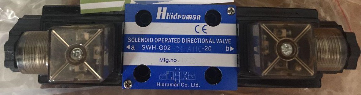
CETOP valves are standardized hydraulic directional control valves used to control the direction, start, stop, and routing of hydraulic fluid in industrial and mobile hydraulic systems.
Hidroman supplies CETOP directional control valves for hydraulic power units, hydraulic cylinders, hydraulic motors, presses, industrial machinery, automation systems, mobile equipment, and custom hydraulic applications.
Available configurations include 4/2 and 4/3 directional valves, solenoid-operated valves, manual control options, and hydraulic control configurations. Depending on the selected model, CETOP valves can support flow rates from 20 to 600 L/min and operating pressures up to 420 bar.
A CETOP valve is a hydraulic control valve designed around standardized mounting dimensions. CETOP standards help ensure compatibility between the valve, subplate, manifold, and hydraulic system.
CETOP valves are commonly associated with ISO 4401 mounting patterns, making them widely used in industrial hydraulic systems where standardized installation and easier maintenance are important.
A properly selected CETOP valve controls hydraulic flow to actuators such as:
For OEM applications, standardized CETOP mounting also makes valve replacement and system maintenance easier.
Hidroman provides CETOP hydraulic valve solutions for a wide range of hydraulic applications.
Depending on the application, available configurations can include:
|
Specification |
Available Options |
|
Valve type |
4/2 and 4/3 directional control valves |
|
Nominal sizes |
NG04, NG06, NG10, NG16, NG25, NG32 |
|
Control |
Solenoid, manual, hydraulic |
|
Flow rate |
20–600 L/min |
|
Operating pressure |
Up to 420 bar, depending on model |
|
Mounting standard |
CETOP / ISO 4401 |
|
Coil voltage |
12 VDC, 24 VDC, 205 VDC, 230 VAC and other options |
|
Return configuration |
Model dependent |
|
Manual override |
Available on selected models |
|
Seals |
NBR and application-specific alternatives |
Actual pressure, flow, spool configuration, coil voltage, and sealing specifications depend on the selected valve model.
A 4/2 CETOP directional control valve provides two valve positions for controlling the direction of hydraulic flow.
These valves are commonly used to control hydraulic cylinders and other double-acting actuators.
For example, a 4/2 valve can direct hydraulic fluid to extend or retract a hydraulic cylinder. Solenoid-operated versions can be controlled by a PLC, electrical control panel, or machine automation system.
Typical applications include:
A 4/3 CETOP valve provides three spool positions and is used when the hydraulic circuit requires an additional center position.
The center position can be selected according to the hydraulic circuit design. Depending on the spool configuration, the center position may block, connect, or redirect specific hydraulic ports.
This makes 4/3 CETOP valves suitable for applications where the actuator must be stopped, the pump flow must be unloaded, or a specific hydraulic circuit condition must be maintained when the valve is in its neutral position.
Correct spool selection is critical because the center configuration directly affects system behavior.
Solenoid CETOP valves use an electrical coil to move the valve spool and change the direction of hydraulic flow.
They are widely used in automated hydraulic systems because they can be controlled electronically by:
Common coil options include 12 VDC, 24 VDC, and 230 VAC, depending on the valve model and application requirements.
When selecting a solenoid-operated CETOP valve, the electrical voltage, connector configuration, duty cycle, hydraulic pressure, flow rate, and operating environment should all be considered.
CETOP valves are available in different nominal sizes to accommodate different hydraulic flow requirements.
Common sizes include:
CETOP 03
CETOP 03 is widely used in compact and medium-flow hydraulic systems. It is frequently found in industrial machinery, hydraulic power units, automation systems, and cylinder control applications.
CETOP 05
CETOP 05 provides a larger flow capacity than smaller CETOP valve sizes and is suitable for hydraulic systems requiring increased flow.
Larger CETOP valve sizes are used in applications where significantly higher hydraulic flow is required.
The correct size should not be selected based solely on physical dimensions. Flow rate, pressure drop, maximum operating pressure, spool configuration, and actuator requirements should be evaluated together.
CETOP hydraulic valves are commonly associated with standardized mounting interfaces based on ISO 4401.
The standardized mounting pattern provides important advantages for hydraulic system manufacturers and maintenance teams.
These advantages include:
Before replacing an existing valve, the mounting pattern and valve interface should always be verified.
CETOP directional control valves are used across a wide range of hydraulic applications.
Common industries and applications include:
Industrial Machinery
CETOP valves are used in manufacturing equipment, automated machinery, production lines, and hydraulic control systems.
Hydraulic Presses
They can control hydraulic cylinders used for pressing, forming, clamping, and material processing.
Mobile Equipment
CETOP hydraulic valves can be incorporated into selected mobile and off-road hydraulic systems where standardized valve mounting is suitable.
Mining Equipment
Heavy-duty hydraulic systems used in mining equipment can require high-pressure directional control valves for cylinders and other hydraulic actuators.
Construction Equipment
Hydraulic control valves are used to manage cylinder and motor functions in construction machinery and specialized equipment.
Agricultural Machinery
CETOP valves can be used in agricultural machinery where reliable hydraulic control and standardized installation are required.
Hydraulic Power Units
CETOP valves are frequently integrated into hydraulic power units (HPUs) to control connected cylinders, motors, and other hydraulic functions.
Test Systems
Hydraulic test benches and custom test systems can use CETOP valves for controlling hydraulic circuits and test sequences.
Selecting a CETOP valve should be based on the complete hydraulic application rather than only the valve connection size.
Determine the maximum pressure that the valve will experience during operation.
The valve's rated pressure should be appropriate for the actual system pressure and operating conditions.
Determine the maximum hydraulic flow through the valve.
An undersized valve can create excessive pressure drop, heat generation, and reduced system performance.
Select the appropriate nominal valve size based on the required flow and the existing mounting interface.
Common sizes include:
CETOP 03, CETOP 05, CETOP 07, CETOP 08 and larger configurations.
The spool configuration determines how hydraulic ports are connected in each valve position.
For 4/3 valves, the center condition is particularly important because it affects the behavior of the pump, actuator, and return circuit when the valve is in neutral.
For solenoid-operated valves, the coil voltage must match the machine's electrical control system.
Typical options include:
The exact available voltage depends on the valve model.
The hydraulic fluid, operating temperature, pressure, contamination level, and chemical compatibility should be considered when selecting seals and valve materials.
For outdoor, mobile, mining, construction, or other demanding applications, environmental conditions should also be considered.
Temperature, moisture, contamination, vibration, and duty cycle can all affect valve performance and service life.
Standardized hydraulic valves can simplify both new machine design and maintenance.
Key advantages include:
Standardized mounting:
CETOP valves can be installed on compatible subplates and manifolds without redesigning the complete hydraulic circuit.
Simplified maintenance:
Standardized interfaces can make replacement and servicing easier.
Flexible system design:
Different valve configurations can be integrated into the same hydraulic architecture when the mounting interface is compatible.
OEM-friendly design:
Standardized hydraulic components can simplify sourcing, machine production, service, and spare-parts management.
CETOP Valve Replacement
When replacing an existing CETOP valve, the replacement should not be selected based only on the valve's external dimensions.
Check the following information:
If any of these specifications differ, the replacement valve may not operate correctly even if the physical mounting appears compatible.
For OEM machine manufacturers, selecting the correct hydraulic directional control valve is an important part of hydraulic system design.
Hidroman can support OEM and custom hydraulic projects by evaluating the required:
This approach helps ensure that the selected valve is appropriate for the complete hydraulic circuit rather than being selected only by nominal size.
Hidroman supplies CETOP hydraulic directional control valves for industrial machinery, hydraulic power units, mobile equipment, test systems, and OEM applications.
Our engineering approach focuses on selecting hydraulic components according to the actual requirements of the system.
For a CETOP valve quotation or technical recommendation, provide the available information about your system, including pressure, flow rate, CETOP size, spool configuration, electrical voltage, hydraulic fluid, and application.
Hidroman can then evaluate the required configuration and help identify a suitable CETOP valve solution.
What is a CETOP valve?
A CETOP valve is a standardized hydraulic valve designed with a defined mounting interface. CETOP directional control valves are commonly used to control hydraulic flow to cylinders and hydraulic motors.
What does a CETOP directional control valve do?
A CETOP directional control valve controls the direction and routing of hydraulic fluid within a hydraulic circuit. It can be used to extend, retract, stop, or otherwise control hydraulic actuators depending on the spool configuration.
What is CETOP 03?
CETOP 03 is a common nominal size for hydraulic directional control valves with a standardized mounting interface associated with ISO 4401.
What is the difference between a CETOP 4/2 and 4/3 valve?
A 4/2 valve has two spool positions, while a 4/3 valve has three positions. The additional center position of a 4/3 valve allows more control over the hydraulic circuit when the valve is in its neutral condition.
What pressure can a CETOP valve handle?
The maximum pressure depends on the specific valve model. Hidroman's CETOP valve range includes configurations rated for applications up to 420 bar, depending on the selected product.
What flow rates are available?
Depending on the valve size and model, Hidroman CETOP valves can be configured for applications requiring approximately 20 to 600 L/min.
Are CETOP valves suitable for hydraulic power units?
Yes. CETOP directional control valves are widely used in hydraulic power units to control hydraulic cylinders, motors, and other actuators.
Are CETOP valves suitable for OEM applications?
Yes. Standardized CETOP mounting interfaces make these valves suitable for many OEM hydraulic systems, especially when consistent component sourcing and simplified maintenance are important.
How do I select the right CETOP valve?
Start with the required operating pressure, maximum flow rate, CETOP/ISO 4401 mounting size, spool configuration, electrical voltage, hydraulic fluid, and application. These parameters should be evaluated together before selecting the valve.
Request a CETOP Valve Quote
Looking for CETOP valves for an industrial, mobile, or OEM hydraulic system?
Send Hidroman your required flow rate, operating pressure, CETOP size, spool configuration, coil voltage, and application details.
Our team can help determine the appropriate CETOP directional control valve configuration for your hydraulic system.
Name Type Cover Nominal voltage/current type Piston type Model
HK 41 3151 0101 C1 R 4/2 positive (closed) 12 VDC 51 [PB/AT]-[PA/BT] Spring reset
Despite rigorous testing, we cannot completely prevent errors and accept no responsibility for the information provided.
Magnetic Road Valve NG 6 Name Type Cover Nominal voltage/current type Piston type Model
HK 41 3151 0101 C1 Q 4/2 positive (closed) 24 VDC 51 [PB/AT]-[PA/BT] Spring reset
HK 41 3151 0101 C1 G 4/2 positive (closed) 205 VDC 51 [PB/AT]-[PA/BT] Spring reset
HK 41 3151 0101 C1 7 4/2 positive (closed) 230 VAC 50 Hz 51 [PB/AT]-[PA/BT] Spring reset
HK 41 3111 0101 C1 R 4/2 negative (open) 12 VDC 11 [PB/AT]-[PA/BT] Spring reset
HK 41 3111 0101 C1 Q 4/2 negative (open) 24 VDC 11 [PB/AT]-[PA/BT] Spring reset
HK 41 3111 0101 C1 G 4/2 negative (open) 205 VDC 11 [PB/AT]-[PA/BT] Spring reset
HK 41 3111 0101 C1 7 4/2 negative (open) 230 VAC 50 Hz 11 [PB/AT]-[PA/BT] Spring reset
HK 41 3151 0201 C1 R 4/2 positive (closed) 12 VDC 51 [PB/AT]-[PA/BT] Spring reset
HK 41 3151 0201 C1 Q 4/2 positive (closed) 24 VDC 51 [PB/AT]-[PA/BT] Spring reset
HK 41 3151 0201 C1 G 4/2 positive (closed) 205 VDC 51 [PB/AT]-[PA/BT] Spring reset
HK 41 3151 0201 C1 7 4/2 positive (closed) 230 VAC 50 Hz 51 [PB/AT]-[PA/BT] Spring reset
Despite meticulous testing, we cannot completely prevent errors and accept no responsibility for the information provided.
HK 41 C1 (7/G/Q/R) Magnetic Road Valve NG 6 Name Type Cover Nominal voltage/current type Piston type Model
HK 41 3101 0601 C1 R 4/2 negative (open) 12 VDC 01 [PB/AT]-[ABPT] Spring reset
HK 41 3101 0601 C1 Q 4/2 negative (open) 24 VDC 01 [PB/AT]-[ABPT] Spring reset
HK 41 3101 0601 C1 G 4/2 negative (open) 205 VDC 01 [PB/AT]-[ABPT] Spring reset
HK 41 3101 0601 C1 7 4/2 negative (open) 230 VAC 50 Hz 01 [PB/AT]-[ABPT] Spring reset
HK 41 3103 0601 C1 R 4/2 positive (closed) 12 VDC 03 [PB/AT]-[A/B/P/T] Spring reset
HK 41 3103 0601 C1 Q 4/2 positive (closed) 24 VDC 03 [PB/AT]-[A/B/P/T] Spring reset
HK 41 3103 0601 C1 G 4/2 positive (closed) 205 VDC 03 [PB/AT]-[A/B/P/T] Spring reset
HK 41 3103 0601 C1 7 4/2 positive (closed) 230 VAC 50 Hz 03 [PB/AT]-[A/B/P/T] Spring reset
HK 41 3108 0601 C1 R 4/2 positive (closed) 12 VDC 08 [PB/AT]-[ABT/P] Spring reset
HK 41 3108 0601 C1 Q 4/2 positive (closed) 24 VDC 08 [PB/AT]-[ABT/P] Spring reset
HK 41 3108 0601 C1 G 4/2 positive (closed) 205 VDC 08 [PB/AT]-[ABT/P] Spring reset
HK 41 3108 0601 C1 7 4/2 positive (closed) 230 VAC 50 Hz 08 [PB/AT]-[ABT/P] Spring reset
Despite meticulous testing, we cannot completely prevent errors and accept no responsibility for the information provided.
HK 41 C1 (7/G/Q/R) Magnetic Road Valve NG 6 Name Type Cover Nominal voltage/current type Piston type Model
HK 41 3107 0601 C1 R 4/2 negative (open) 12 VDC 07 [PA/BT]-[A/B/PT] Spring reset
HK 41 3107 0601 C1 Q 4/2 negative (open) 24 VDC 07 [PA/BT]-[A/B/PT] Spring reset
HK 41 3107 0601 C1 G 4/2 negative (open) 205 VDC 07 [PA/BT]-[A/B/PT] Spring reset
HK 41 3107 0601 C1 7 4/2 negative (open) 230 VAC 50 Hz 07 [PA/BT]-[A/B/PT] Spring Reset
HK 41 3152 0101 C1 R 4/2 negative (open) 12 VDC 52 [PB/A/T]-[PA/B/T] Spring reset
HK 41 3152 0101 C1 Q 4/2 negative (open) 24 VDC 52 [PB/A/T]-[PA/B/T] Spring reset
HK 41 3152 0101 C1 G 4/2 negative (open) 205 VDC 52 [PB/A/T]-[PA/B/T] Spring reset
HK 41 3152 0101 C1 7 4/2 negative (open) 230 VAC 50 Hz 52 [PB/A/T]-[PA/B/T] Spring reset
HK 41 3201 0302 C1 R 4/3 negative (open) 12 VDC 01 [PB/AT]-[ABPT]-[PA/BT] Spring reset to 0
HK 41 3201 0302 C1 Q 4/3 negative (open) 24 VDC 01 [PB/AT]-[ABPT]-[PA/BT] Spring reset to 0
HK 41 3201 0302 C1 G 4/3 negative (open) 205 VDC 01 [PB/AT]-[ABPT]-[PA/BT] Spring reset to 0
Despite meticulous testing, we cannot completely prevent errors and accept no responsibility for the information provided.
HK 41 C1 (7/G/Q/R) Magnetic Road Valve NG 6 Name Type Cover Nominal voltage/current type Piston type Model
HK 41 3201 0302 C1 7 4/3 negative (open) 230 VAC 50 Hz 01 [PB/AT]-[ABPT]-[PA/BT] Spring reset to 0
HK 41 3203 0302 C1 R 4/3 positive (closed) 12 VDC 03 [PB/AT]-[A/B/P/T]-[PA/BT] Spring reset to 0
HK 41 3203 0302 C1 Q 4/3 positive (closed) 24 VDC 03 [PB/AT]-[A/B/P/T]-[PA/BT] Spring reset to 0
HK 41 3203 0302 C1 G 4/3 positive (closed) 205 VDC 03 [PB/AT]-[A/B/P/T]-[PA/BT] Spring reset to 0
HK 41 3203 0302 C1 7 4/3 positive (closed) 230 VAC 50 Hz 03 [PB/AT]-[A/B/P/T]-[PA/BT] Spring reset to 0
HK 41 3208 0302 C1 R 4/3 positive (closed) 12 VDC 08 [PB/AT]-[ABT/P]-[PA/BT] Spring reset to 0
HK 41 3208 0302 C1 Q 4/3 positive (closed) 24 VDC 08 [PB/AT]-[ABT/P]-[PA/BT] Spring reset to 0
HK 41 3208 0302 C1 G 4/3 positive (closed) 205 VDC 08 [PB/AT]-[ABT/P]-[PA/BT] Spring reset to 0
HK 41 3208 0302 C1 7 4/3 positive (closed) 230 VAC 50 Hz 08 [PB/AT]-[ABT/P]-[PA/BT] Spring reset to 0
HK 41 3207 0302 C1 R 4/3 negative (open) 12 VDC 07 [PA/BT]-[A/B/PT]-[PB/AT] Spring reset
HK 41 3207 0302 C1 Q 4/3 negative (open) 24 VDC 07 [PA/BT]-[A/B/PT]-[PB/AT] Spring reset
HK 41 3207 0302 C1 G 4/3 negative (open) 205 VDC 07 [PA/BT]-[A/B/PT]-[P